My first electronic hardware: a remote pc-switch for Home Assistant

A friend recently asked me, if I know a smart home switch that runs 5V and it is pretty small. His use case was to turn on/off his HTPC in the living room. This was accomplished via infrared and a Logitech Harmony which he wants to retire.
He shared the almost perfect device for this use case. The SilverStone ES03-WiFi. The only drawback is the app which is needed and is an absolute no-go.
There is no need to open your PC switch to the internet and a probably insecure app. Despite the fact that SilverStone or whoever is running the infrastructure for the app can shut down their servers at any time. This will render your device as a useless purchase.
After some research, I found 2 similar devices also by SilverStone. The SST-ES02-PCIe and SST-ES02-USB. Both work with some kind of 2.4GHz remote but use a different form factor. Still, no option because the switch should be integrated with his smart home which runs Home Assistant.
Phase 1: Check requirements
Here are the most important features and constraints for the desired device:
- Local connectivity without internet required
- No separate app
- Ability to use with Home Assistant
- small (Needs to fit into a PC)
- powered by the PC itself
Phase 2: Research
After some research, I found similar projects. The guy from the YouTube channel The Hook Up (highly recommended) had done something like that.
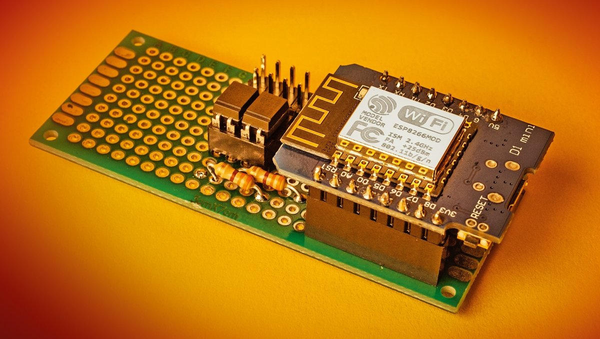
Then there was a German Article by heise on how to turn on a PC with ESP8266:
And another blog post I randomly found on the internet:
So it looked like an optocoupler was used in all projects to protect the motherboard and the ESP8266 with galvanic isolation. Then we can use one of the pins from the ESP8266 to create a short circuit for a small amount of time via software to power on/off or reset the PC.
Since I was playing with ESPHome anyway the last weeks/months I thought this could be the perfect use case for this.
Phase 3: Prototype on a breadboard
Here you see my first breadboard prototype:
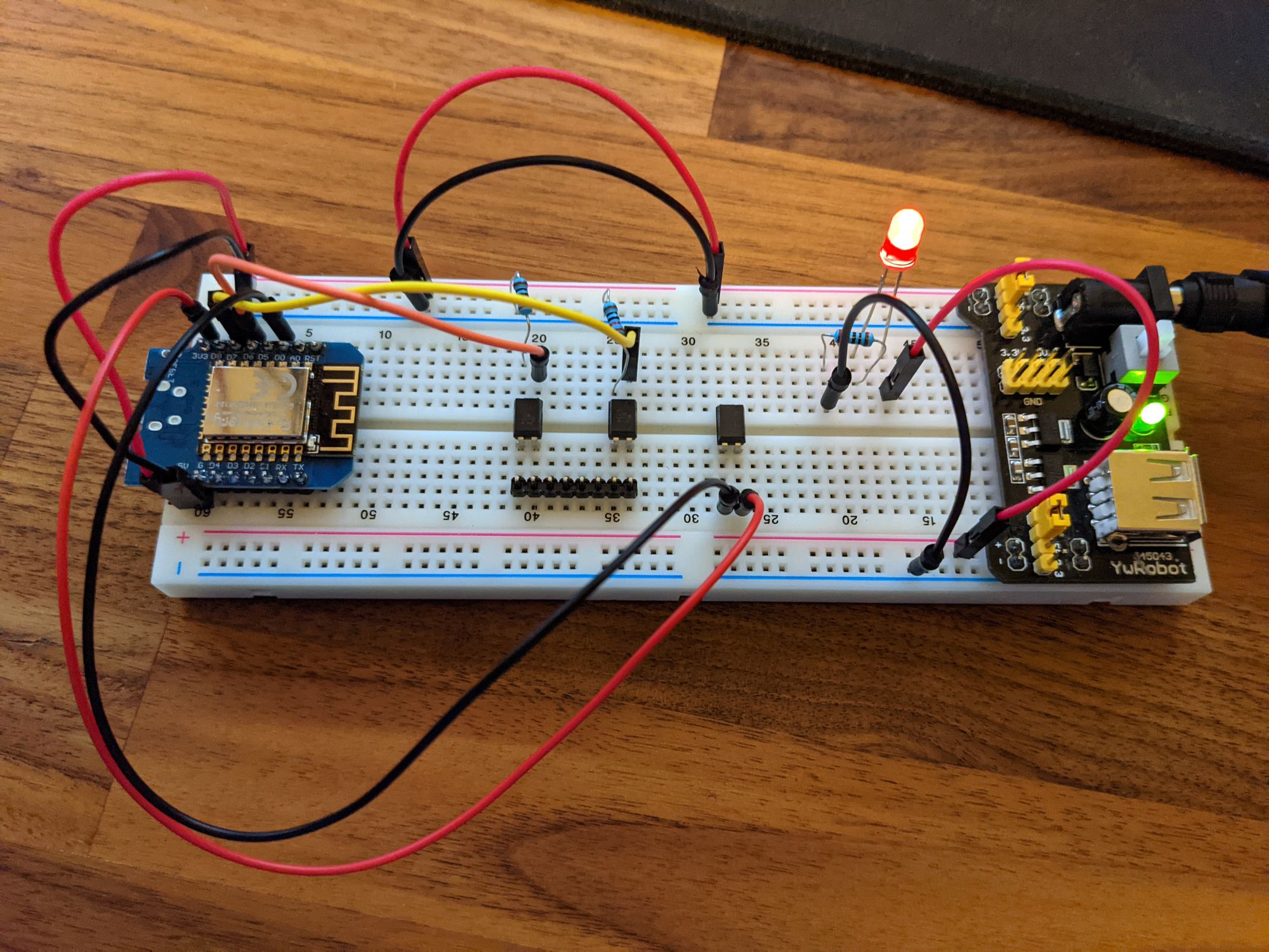
On the YwRobot Power Supply which I got in some electronics kit years ago. This is connected to a simple wall power supply.
On the left, we have the ESP8266-12F from AZDelivery. Connected to power.
Also, I D6 and D7 are connected to one of the optocouplers. One for reset, the other for power. (In the middle part)
On the right is just a small test circuit. Not important here.
Phase 4: The Code - ESPHome again
That was relatively straightforward. We just need to create 2 switches for the power connector. The first one is for normal power, which will be turned on for 300 ms. The second switch can be used for hard shutdown with something like 5000 ms (5 seconds).
The reset connection is basically the same but just with another pin. Will do that later.
esphome:
  name: pc-switch
  platform: ESP8266
  board: nodemcuv2

# Enable logging
logger:

# Enable Home Assistant API
api:

# Put ota password here
ota:
  password: ""

# Your wifi config
wifi:
  # ssid: ""
  # password: ""

  # Enable fallback hotspot (captive portal) in case wifi connection fails
  ap:
    ssid: "PC-Switch Fallback Hotspot"
    password: "fallback-wifi"

captive_portal:

switch:
  - platform: gpio
    pin: D6
    id: power
    name: "Power toogle"
    icon: "mdi:PC"
    on_turn_on:
    - delay: 300ms
    - switch.turn_off: power

  - platform: gpio
    pin: D6
    id: force_power
    name: "Force power off"
    icon: "mdi:PC"
    on_turn_on:
    - delay: 5000ms
    - switch.turn_off: force_power
The files can be found on my GitHub repo (in case I will update this) :
Phase 5: Hand Soldered Prototype
Uff, I am not good at soldering. For some reason 1 of the pins also did not work. Could figure out why. Should suffice as a prototype.
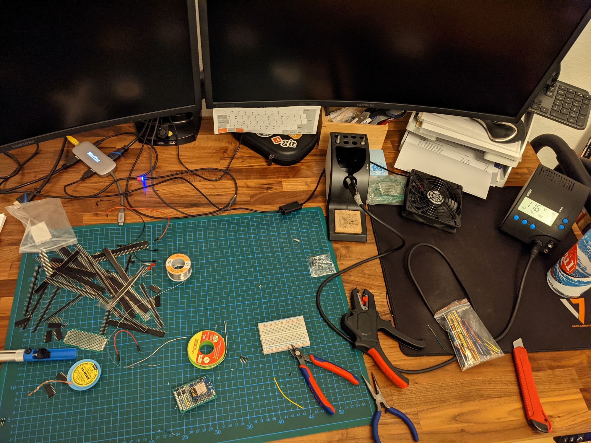
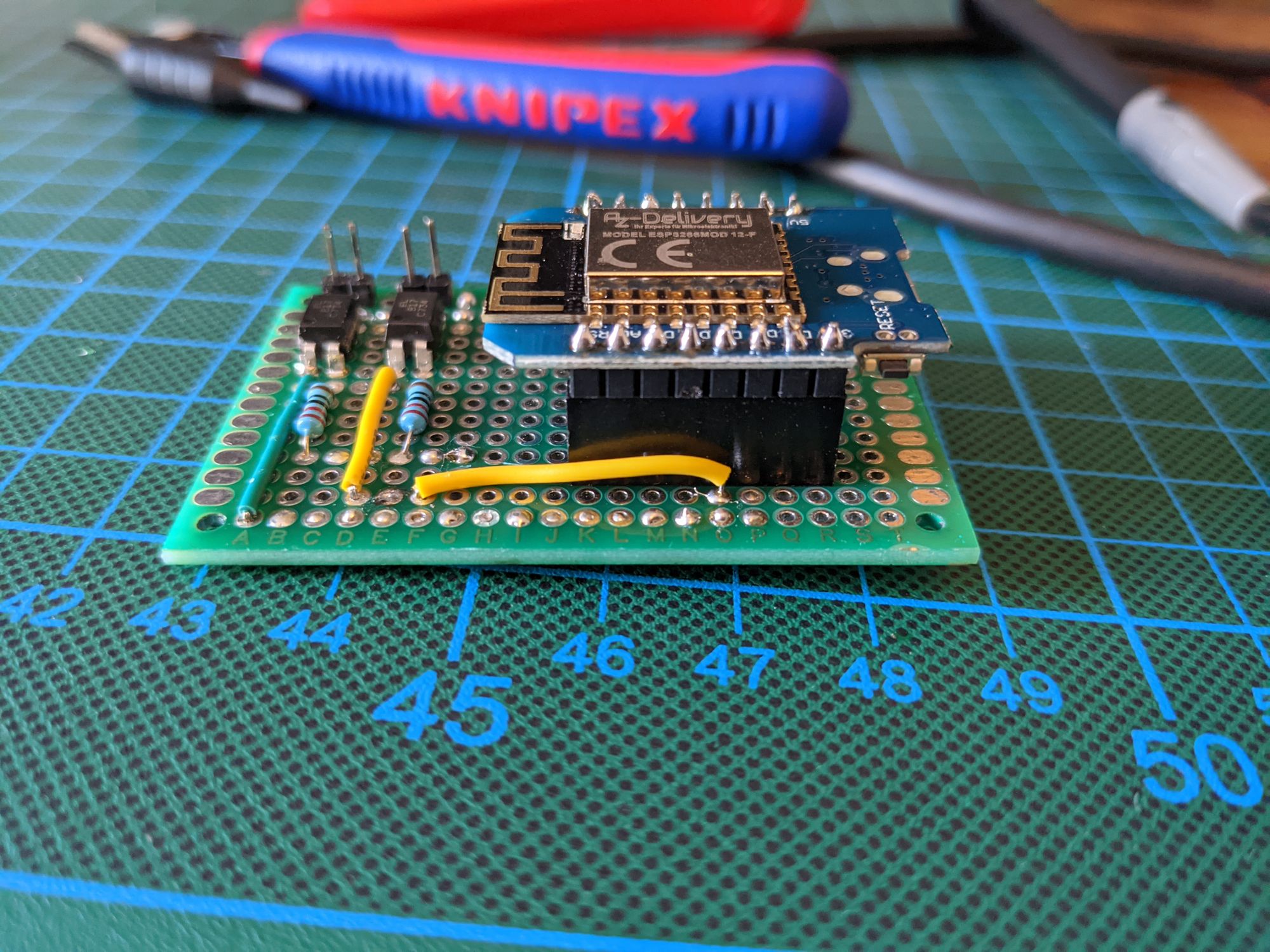
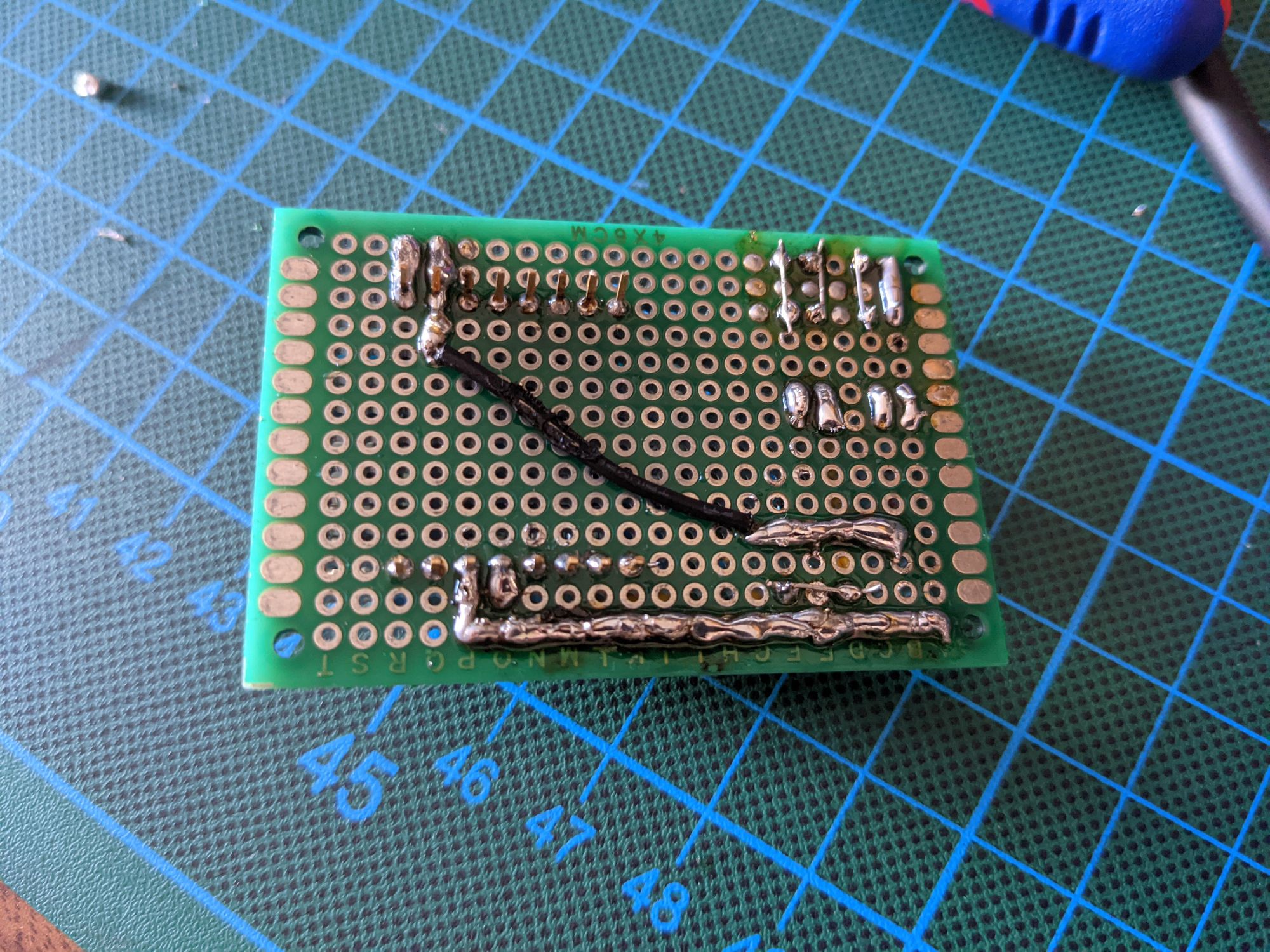
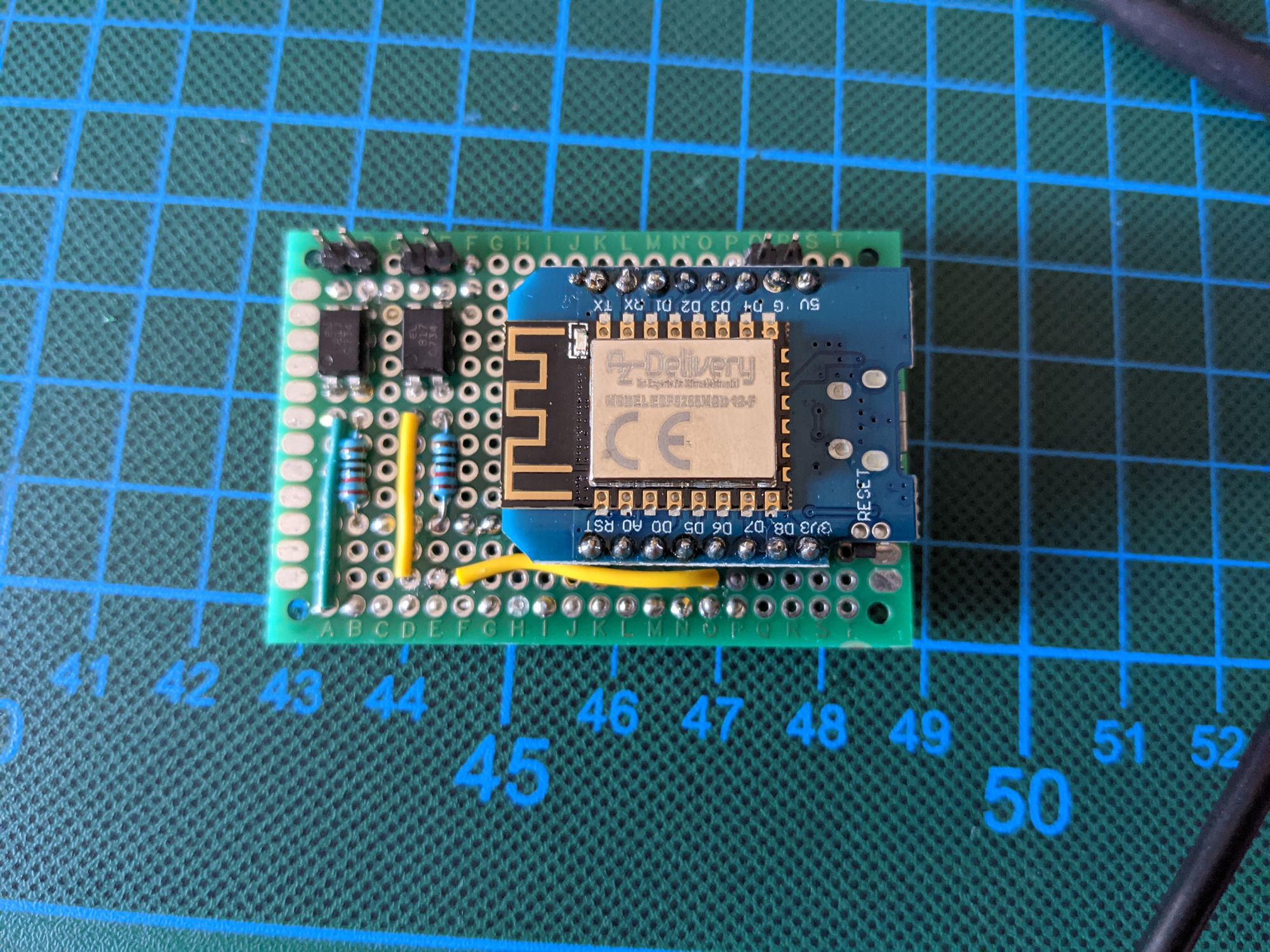
That is the very basic idea.
Now I need to figure out how to measure the status of the PC itself. Not 100 % sure about that. I have read somewhere that using the PC power led is not a good idea. Do not remember why though.
Maybe I can use the PC mainboard buzzer connectors?
Please let me know if you have any suggestions regarding this project. I am just starting in this space and I bet there are WAY more knowledgeable people out there.
If this is figured out I will start building a PCB for this. How cool would that be?
If you find this interesting hit subscribe and do not miss any updates on my shenanigans. Feel free to share this with your friends as well.
And please reach out to me, if you want this build. This will increase pressure on me to finish this ? Also reach out to me if you know a thing or too or did catch a mistake!
Have a great day!


