PokyPow Prototype Debugging

Hey nerds 🤓
I had a weird issue I could not understand. So here it goes.
When I got the new PokyPow from Soldered, I had to adjust the code a bit, since we now have sensors for button presses on the PC case side. Then we evaluated if we have the child lock active. If not, then we short the power and reset button on the motherboard to turn on/off or reset the PC.
So far, so good. It worked on my gaming PC. However, connecting it to a different mainboard was not working. So I started by connecting one cable after the other. Connecting everything except the power and reset button on the mainboard side, the board was working fine.
As soon as I connected the power or reset button to the PokyPow the PokyPow would just shut down.
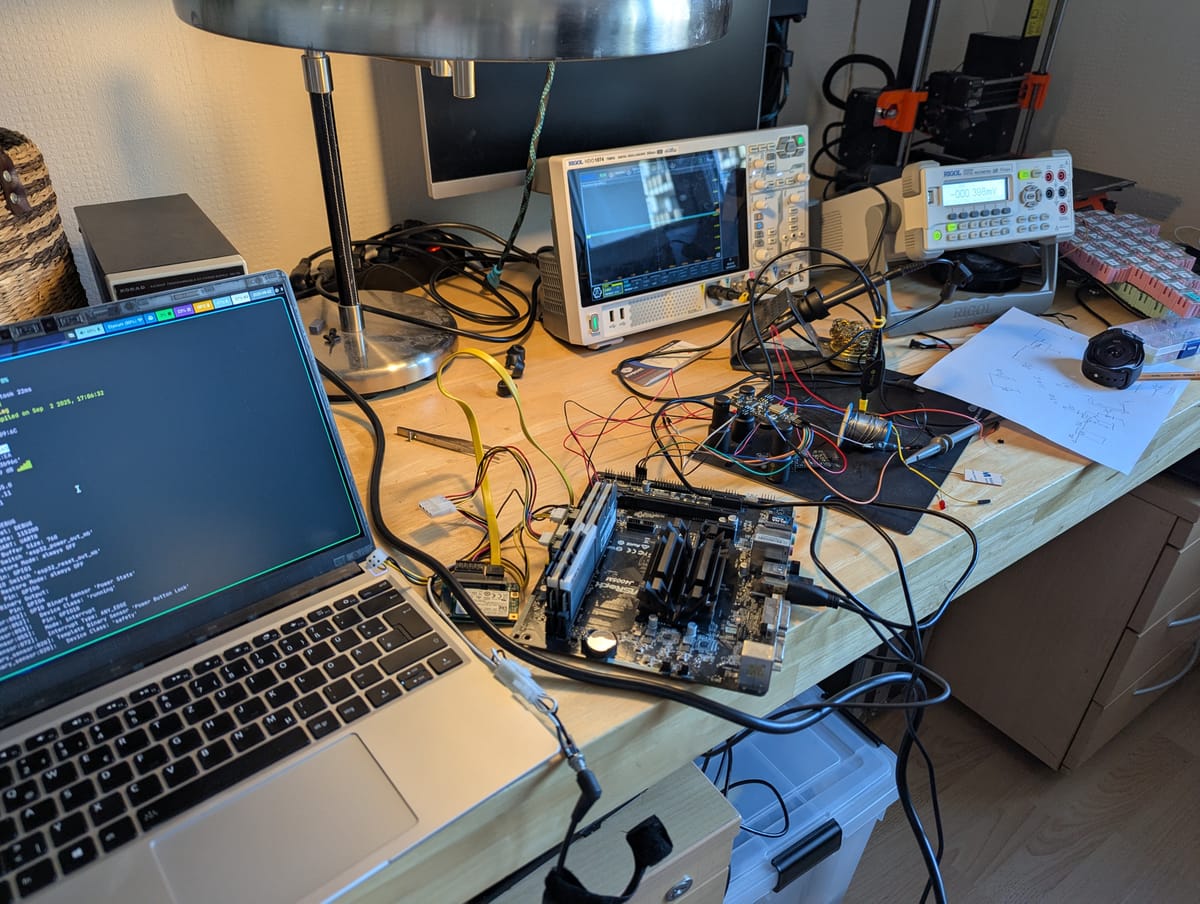
I called my friend and hardware engineer Niklas. He has the knowledge and the equipment at home to debug these issues. I just have a multimeter and a simple understanding of electronics.
Why the shutdown?
It looks like the one random mainboard I had lying around saved my bacon 🥓. There was some current backflow of 40mA from the power button. We think that led the ESP32 to get into some failsafe mode: "Nah man, this is too much. Gonne shutdown!"
After putting a diode in the circuit, we could prevent the current backflow and the PokyPow did not shut down anymore when connecting the power and reset button from the mainboard.
When triggering the button via the web interface, the mainboard did not turn on. 🤔
Why does the power trigger not turn on/off the mainboard?
We checked the voltage on the power pins of my mainboards. The one that worked had perfect 3.3V. The one that did not work had 3.7V. More than the ESP32C3 can provide. Looks like the mainboard also expected this voltage, and 3.3V was just not enough.
Solution
When I got the board, the Soldered team suggested a change: Switch from MOSFETs to optocouplers again. Because that would allow using an external power supply. With MOSFETs, you can only use the PokyPow as long as it is plugged into the same PC.
Luckily, the optocouplers are the solution for the problems we discovered as well (current backflow, voltage not high enough).
So we are going back to optocouplers.
There were also some minor things:
- Wrong labeling on the backside of the board
- a male instead of a female USB 2.0 connector
- ESPHome did throw a warning about using a strapping pin. Since we have 2 pins left, we are moving to another pin. That way, people will not be confused when they compile the firmware themself.
I already paid for the next prototype. Let's hope it comes soon 🤞
That is it for now.
Feel free to reply to this via mail, comment down below, or join my Discord!
Enjoy your day!